Entering Loads: Horizontal Members
First, see the The Loads Tab topic for entering loads being placed on the member being designed. For general information on loads, refer to the Understanding Load Input Type Options topic.
Self-weight
Self-weight is the weight in lbs/ft of a product. This is considered a dead load acting on the full length of the member. Self-weight is used only when member type is flush beam or drop beam. ForteWEB software automatically includes the product self-weight as part of the dead load acting on the full span of the member. When the member type selected is joists there is no self-weight; joist weight is assumed to be included in the area base dead load.
Load Display
The graphical load display shows all loads acting on the member using a proportioning algorithm that gives users and idea of the load magnitude relationship among loads by comparing the lowest to the highest load magnitude.
Loads starting and ending locations are always measured along the horizontal projection, even for pitched members. The load display will not adjust loads as being perpendicular to a pitched member; all loads are depicted as acting on the horizontal projection. This is not always correct, but it is done this way for simplicity. Internally, analysis will be done with all loads acting perpendicular to the member. All necessary slope corrections will automatically be performed by the analysis engine.
Use the Tab key to navigate the fields of the grid. Use the up/down arrow keys to select values from the drop-down menus. Using Alt+ up/down will display the list of available selections.
Type
Select the type of load from the drop-down menu. Some load types disable certain fields within the grid. Load types include:
- Point (lb)
- Point (PLF)
- Uniform (PLF)
- Uniform (PSF)
- Tapered (PLF)
- Tapered (PSF)
Point loads in lbs and uniform loads in lbs per foot (PLF) are non-spacing sensitive. For example, if a repetitive member such as a joist has any of these load types, when the on-center spacing changes, the load magnitudes don't get adjusted for spacing changes.
User defined Uniform PLF load inputs are not adjusted by a considered OC spacing. If you are linking loads from this calc, choose the correct load developed OC spacing in the Product Selection tab.
Full Length
Select this field if the load will span the entire length of the member. If you select this field, "Across Full Length" displays in the Location fields. The system defaults both the start and end location values. The load will always cover the full length of the member, even if the length of the member changes as spans are changed, added, or deleted.
If you deselect this field, the actual start and end location display.
Location
Enter the beginning point and end point of the load. For example, if the load is 5' long and in the middle of a 15' member, enter 5.0 for the beginning point of the load and 10.0 for the end point of the load.
Point loads only have one location and the grid automatically adjusts for this.
For pitched members, load locations are always measured along the horizontal projection.
For easier dimensioning for load locations, see Location Shorthand section at the bottom of this page.
Tributary Width
This option is only available for non-joist members. Only the following load types are adjusted by Tributary Width:
- Point(PLF) is multiplied by the tributary width to arrive at a Point(lb) load on the member.
- Uniform(PSF) or Tapered(PSF) is multiplied by the tributary width to arrive at a Uniform(PLF) or Tapered(PLF) load on the member.
When you add a load, the system automatically generates a default Tributary Width of 1’. You can change this setting with a different value if necessary.
Line load in lbs/ft = area load * tributary width
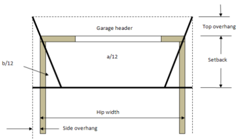
The area load is defined by the user and the user chooses how much of that area load acts on the member by choosing the tributary width. In the figure below we are trying to size the garage header under the hip. What would be the tributary width to plug into ForteWEB?

Tributary width = Setback/2 + top overhang
Tributary width is the length on which the area load works, not the distance between the member and the nearest structural support, a hip girder in this case (it would be half this distance). The overhang is fully carried by the garage header so the full overhang length is added to the tributary width.
Load Placement
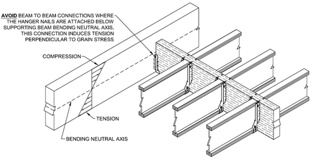
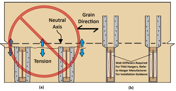
This option is only available for flush and drop beam for roof and floor applications for consideration with multiple member and filler block connections. Regardless of load placement selected, loads are assumed to be applied above the neutral axis, without consideration for additional mechanical reinforcement.
Wood's strength varies based on the direction of the load relative to the grain orientation. Typically, wood can resist greater stress when loaded parallel to the grain rather than perpendicular to it. The National Design Specification® (NDS) for Wood Construction advises against designs that induce tension perpendicular to the grain due to its minimal resistance to such stress. Engineered wood products like Trus Joist® Parallam® PSL, Microllam® LVL, and Timberstrand® LSL are manufactured with their grain aligned parallel to the length of the member, offering no inherent advantage for resisting tension perpendicular to the grain. Proper design and detailing are essential to prevent tension perpendicular to grain loading situations, which can lead to sudden and unexpected failures. Tension perpendicular to the grain can cause non-ductile failures, posing significant structural risks. Such failures can occur without warning, potentially leaving occupants unaware of impending issues. To mitigate these risks, it is recommended to place fasteners above the neutral axis using taller hangers or reinforce the supporting beam with an engineer's assistance.


Select the appropriate placement from the drop-down menu:
- Top
- Front Side
- Back Side
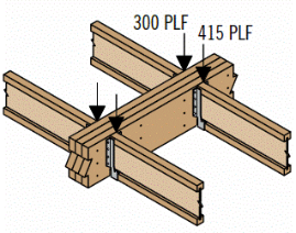
The 300 plf in this example would be defined as Back Side, whereas the 415 plf would be defined as Front Side. Top placed loads would be carried by all plies simultaneously.

Dead Load and Live Load
These fields are available only when you select the Commercial building class on the Member tab. The system automatically populates the values in these fields based upon the selected Occupancy Type. However, you may edit these fields if necessary.
Dead
Enter the amount of dead load being placed on the member.
Roof Slope
The pitch of the roof.
Adjusted Dead
Uniform (PSF) dead loads are adjusted when the roof pitch is greater than zero. If the roof pitch is zero (the default) no adjustment is made.
Floor Live
Enter the amount of floor live load being placed on the member.
Roof Live
Enter the amount roof live load being placed on the member. This value applies to the United States only.
Partition Load
In office buildings and in other buildings where wall partition locations are subjected to change, provisions for partition weight are made, regardless whether partition walls are included in the construction documents. ForteWEB provides the building code recommended minimum partition loads when you select a relevant floor occupancy. You can change or delete this load.
For IBC, wall partition weight is considered a floor load. For NBCC, wall partition weight is considered a dead load. ForteWEB automatically makes the correct selection based on the selected building code.
This field is available only when you select the Commercial building class on the Level tab.
Snow
Enter the amount of snow load being placed on the member.
Wind
Enter the amount of vertical wind load being placed on the member. Lateral wind load options will appear in the wall header loads tab. Lateral wind load is analyzed:
- Along the full member length
- For simple span wall headers only
- For single ply members only
Seismic
When using non-overstrength seismic loading, enter the vertical seismic load as E=f(Ev,Eh).
When using overstrength seismic loading, enter the QE as the effects of horizontal seismic forces from V, Fpx, or Fp.
For additional information, visit: Seismic Loading Tab Help
Comment
Enter any comments needed to explain the load information.
Lateral Loads (Wind)
Lateral wind load is analyzed:
- Along the full member length
- For simple span wall headers only
- For single ply members only
Location Shorthand
For easier dimensioning when entering a location, you can use the following shorthands to reference various places along the member:
-
R to reference the right end of the member. Enter R - (minus sign) and a distance to specify a location from the outside face of the right support (or right cantilever end).
-
Support number to reference a support. Enter support number - (minus sign) and a distance to dimension from the left face of that support, or support number + (plus sign) and a distance to dimension from the right face of that support.
-
Support number and | (pipe) to reference the center of a support. For example, "2|" would reference the center of support 2. Or you can offset a distance by adding +/- and the distance depending on the direction.
-
M or C to reference the center of the member. Enter M or C alone or add +/- and the distance to offset from the center of the member. So, entering "C + 2.5" would give you the center of the member plus 2.5".
Check out this Location Shorthand video for more information.